Heat flux sensor technology: printed thermopile conductors vs. etched-and-plated
Hukx’s foil heat flux sensors contain full-metal “etched-and-plated” thermopile conductors. Competing models use thermopile conductors made by printing metal-filled inks. Testing at Hukx has revealed shortcomings, in particular the instability of heat flux sensors manufactured using metal-filled inks.* A sensor that is not stable does not reliably perform an accurate and repeatable measurement.
Users may detect stability issues by monitoring the electrical resistance of the heat flux sensor.
Introduction
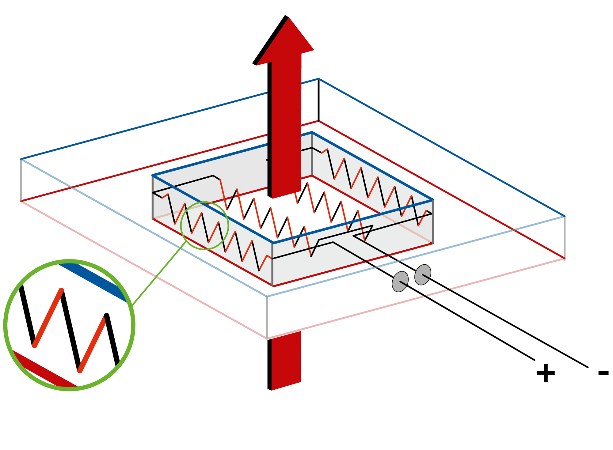
Heat flux sensors measure a temperature difference across a thin layer of material. They typically employ a thermopile, which is manufactured by creating an alternating pattern of two dissimilar conductors, generally metal alloys. See Figure 1.
Printed flexible circuits
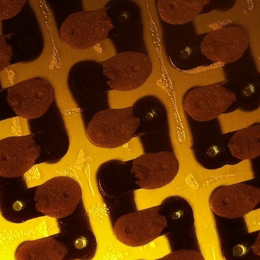
Printed flexible circuits are commonly used in many applications. The electrically conductive inks used in these circuits consist of a plastic base-material filled with small conducting particles, typically copper, nickel or silver. Using an electrical circuit with through-holes and filling up alternate holes with two different conductive inks, you may construct a thermopile, see Figure 2. See also US patent 10 393 598.
Etching and plating
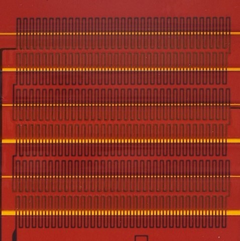
Etching and plating technologies use a metal foil as base-material. By etching material away, and locally plating with another metal, you may construct a thermopile, see Figure 3.
Differences: sensor stability
The differences between the two technologies were revealed in two experiments. They address potential issues with sensor stability, i.e. change in sensitivity.
- stability under high temperature exposure
- stability under bending
An unstable sensor grows increasingly unreliable with time and use. As a result, its uncertainty of the sensitivity, as given in the calibration certificate, is no longer valid. To put test results in perspective: the calibration uncertainties of all sensors involved are 5 %. An instability of just a few percent is significant.
Test results
The sensitivities of the sensors were tested at 20 °C after 1-time bending around a pipe of 25 x 10⁻³ m radius, and after 24 hours of exposure to high temperatures. Sensors were first exposed to 120 and later to 150 °C. The 150 °C is above the rated operating range for printed sensors and only serves to present an indication of what may happen during long-term exposure within the rated 120 °C range. The changes of sensitivity were all relative to an initial measurement by Hukx at 20 °C and were all performed on a flat surface. When determining the sensitivity, the capability to measure changes has a reproducibility in the order of 1 %, asserting that changes of 3 % can meaningfully be detected. In this experiment absolute accuracy is not a factor.
Table 1 test of stability of sensitivity and internal resistance of heat flux sensors based on two manufacturing technologies. Tests were performed before and after 24-hour exposure to high temperatures and before and after bending. Sensors are all rated for long-term use up to 120 °C, and sold as “flexible”, which was confirmed by the sellers: “suitable for bending up to 1.25 x 10⁻³ m radius”. Changes are all relative to those at the start of the test, positive values indicating a higher value after testing.
| sensor technology | test | permanent change of sensitivity | permanent change of resistance |
| [name] | [(V/(W/m²)/(V/(W/m²)] | [Ω / Ω] | |
| etched | bending radius 25 x 10⁻³ m | not detectable (< 3 %) | < 2 % |
| printed | Bending radius 25 x 10⁻³ m | -7 % | +11 % |
| etched | 120 °C | not detectable (< 3 %) | < 2 % |
| printed | 120 °C | + 6 % | + 250 % |
| etched | 150 °C | not detectable (< 3 %) | < 2 % |
| printed | 150 °C | + 16 % | + 1200 % |
Conclusions
- Sensors based on the etching and plating manufacturing technology are stable under bending and high temperature exposure within the rated operating range.
- Sensors based on metal-filled inks must be treated with care and may have stability issues, even under mild exposure.
- Sensors based on metal-filled inks may have different failure mechanisms under bending and under exposure to high temperatures. Comparing test results resistance increases in all tests while sensitivity increases in one test and sensitivity decreases in the other.
Related products

We like having a good technical conversation
Do you have questions, need help finding the right solution, or looking to discuss an instrument for a unique application? Our technical engineers provide expert advise. Contact us now!