How to install a heat flux sensor
Tips and tricks to get the most out of your heat flux measurement
Measuring heat flux is a powerful tool to gain insights in processes. You may measure for example how much heat flows through a wall, or to a specimen that must be cooled. Assuming the right sensor is used, installing this sensor correctly, so that it performs a stable measurement and measures the right heat flux (radiative and convective), is a critical step to get the right data. This paper dives into the do’s and don’ts when installing a heat flux sensor.
Introduction
Heat flux sensors have a wide variety of applications, from thermal performance analysis of thermal insulation, to monitoring of fouling of pipelines and the health monitoring of pigs. Measuring the heat flux can lead to useful insights in processes and system performance. Assuming the right sensor is used, mounting this sensor correctly, so that it performs a stable measurement and measures the right heat flux (radiative and convective), is a critical step to get the right data.
This paper focuses on sensor installation. What are the do’s and don’ts when installing a heat flux sensor; how can you get the best data from your sensor?

General considerations for heat flux measurement
- Use the right sensor for the application. There are many different models, each with their own temperature- and heat flux range. View our complete product range of heat flux sensors.
- See also our video on YouTube: how to measure heat flux.
- Perform a representative measurement. This starts with choosing the right location, representative of the system to be monitored. Use multiple sensors. Representatives may be reviewed using infrared cameras.
Considerations for installation
Regardless of the heat flux sensor type, it is important that it is mounted securely to avoid variations of contact resistance between the sensor and the object on which it is mounted.
- Air gaps between sensor and object may be significant thermal resistances and increase response time. This should be avoided.
- Sensors gradually getting loose essentially produce unreliable (unstable) measurements. Use stable glue or filler. Use high quality cabling and strain relief.
Also, optical properties must match.
- Pay attention to the optical properties of the sensor surface. These must match those of the object the sensor is mounted on.
Mounting
There are various ways to mount a heat flux sensor, depending on the application. Two important parameters are
- temperature range
- the duration of the measurement
These two parameters will help choose the right mounting solution for the heat flux sensor.
Table 1 and the examples at the end of this note will help you review your options.
Always ensure strain relief on the cable to avoid unnecessary stress on the sensor.
Why avoid air gaps
The thermal conductivity of air is in the order of 0.02 W/(m·K). Therefore, even small air gaps are significant thermal resistances.
The thermal conductivity of a plastic or thermal paste is in the order of 0.2 W/(m·K), so for the same thickness, thermal resistance is a factor 10 lower.
Take for example a 0.05 x 10⁻³ m, air gap. This has a thermal resistance of 20 x 10-4 K/(W/m2). This may be compared to 11 x 10-4 K/(W/m2) for FHF05 series or 70 x 10-4 K/(W/m2) for HFP01, so a small air gap produces an increase of thermal resistance of 200 % for FHF and about 30 % for HFP01. Using a filler of 0.05 x 10⁻³ m, with a thermal conductivity around 10 times higher than that of air, the thermal resistance is reduced to 2.5 x 10⁻⁴ K/(W/m2). The contribution of the thermal resistance reduces to about 20 % for FHF05 and 3 % for HFP01.
From this example you can also see that it is not necessary to use high-thermal conductivity tapes. Using a thin normal tape is enough.
An air gap may not only lead to higher thermal resistance for conductive heat, but also to an entirely different radiation balance. An air gap is a “resistance” (a radiation screen) for radiative transfer. If it is filled up, it is no resistance any longer. Watch out in case radiative (far infrared) heat flux is significant. In that case the presence of an air gap may be the dominant source of errors, because a sensor with an air gap acts as a radiation shield, reducing local radiative transfer by a theoretical maximum of 50 %.
Table 1 Options for mounting heat flux sensors. Materials may act to fix the sensor position, but also to fill up airgaps.
| NR | product | duration | rated temperature range | functionality | comments |
| [#] | [description] | [description] | [°C] | [description] | [description] |
| 1 | powerstrip | temporary, easily removable | 15 to 40 | fixation and gap filling | TESA Powerstrip. very easily removable. |
| 2 | glycerin | minutes | to 120 | gap filling only | Filler only for quick experiments; glycerin can be obtained at the local pharmacy. It is safe to use and easily dissolves in water. |
| 3 | toothpaste | days | 40 | gap filling only | Filler only, use with other fixation such as single sided tape
Water-based
Most commercially available toothpastes are suitable |
| 4 | double sided tape | 2 weeks, removable | 40 | fixation and gap filling | TESA 4939 floor laying (carpet) tape combines a high initial bonding power with a residue free removability up to 14 days from the most common surfaces. (needs to be tested individually before usage) |
| 5 | thermal paste | weeks | to 177 | gap filling only | Filler only, use with other fixation such as single sided tape
Silicone oil-based
|
| 6 | silicone glue | permanent | -45 to 200 | fixation and gap filling | Most commercially available silicone glues are suitable
|
| 7 | single sided tape | temporary or permanent | -260 to 150 | fixation only | Fixation only, use with other fillers such as thermal paste
TESA 51408 orange masking tape
Most commercially available Kapton tapes are suitable |
| 8 | magnets | temporary or permanent | to 500 | fixation only | on magnetic surfaces only
for sensors with optional “frame with magnet” only
in case using welded treads or bolting is not |
| 9 | tack welded threads | temporary or permanent | -260 to 1000 | fixation only | For sensors with flanges
Fixation only, use with other fillers such as silicone, graphite sheet material or cements
Usually combined with springs |
| 10 | bolts | temporary or permanent | -260 to 1000 | fixation only | For sensors with flanges
Fixation only, use with other fillers such as silicone, graphite sheet material or cements
Usually combined with springs |
| 11 | silicone gasket | temporary or permanent | to 200 | Gap filling only | Filler only, use with other fixation such as bolts or threads
Users can cut sheets to size |
| 12 | graphite gasket | temporary or permanent | to 500 | Gap filling only | Filler only, use with other fixation such as bolts or threads
ERIKS Ergaflex or similar sheet material
Users can cut sheets to size. |
| 13 | high temperature cement | temporary or permanent | to 1400 | fixation and gap filling | OMEGA high temperature cement |
| Other options for mounting | |||||
| 14 | Cements and epoxies | various | various | various | OMEGA cements and epoxies |
What to do about air gaps
Tapes, sheet (gasket) material, glues, and cement all may be used to fill-up air gaps.
These gaps may occur:
- Because of the nature of the surface. It may not be smooth. Smoothen before installation.
- Because of a curved surface. For all practical purposes, a surface with a radius larger than 5 m is considered “flat”. At smaller radii, use of flexible sensors may be considered. For industrial sensors like IHF01 and IHF02, we may also provide coupling pieces (flat on one side, curved on the other).
Table 1 summarizes the different mounting options.
Why optical properties are important
When heat flux sensors are mounted at a surface, heat will often be transferred by a combination of radiation and convection. For the convective part, the thermal resistance of the sensor should be as low as possible. For the radiative part, the optical surface properties of the sensor should be representative of the surrounding area.
Some points to keep in mind:
- Radiation is not only transmitted in the spectral range that humans can see (visible radiation) but also as non-visible far infrared.
- Blank metal is reflective in the visible as well as in the far infrared.
Paints and plastic coatings, wood and stone absorb in different ranges, depending on their color in the visible range. These materials typically all behave as “black” in the far infrared.
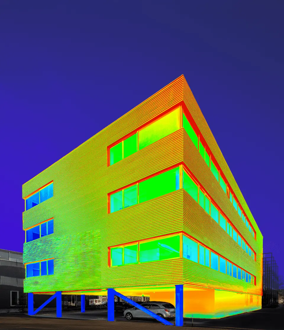
Representativeness may be reviewed using a combination of normal (visible range) and infrared (far infrared range) cameras.
Related products


We like having a good technical conversation
Do you have questions, need help finding the right solution, or looking to discuss an instrument for a unique application? Our technical engineers provide expert advise. Contact us now!